Ways to Differentiate Alternator, Generator & Motor
Content :
1) Principle Electromagnetic Induction
2) Alternator(AC only) Vs Generator(AC/DC) Vs Motor(AC/DC)
3) Brushes VS Brushless Alternator/Motor
4) Synchronous(AC) & Asynchronous Motor(AC)
5) Cylindrical & Salient Pole Rotor
1) Principle Electromagnetic Induction
1) Faraday's Law ; when there is change in magnetic flux, an electro motive force (e.m.f) is induced OR we can say Relative motion between magnet & coil induced EMF
2) Fleming rule use to determine direction of current / Right Hand Rule (motor), Left Hand Rule(generator).
3) Lenz law ; Induced EMF or Voltage direction oppose to the cause of it (magnet motion).
 |
| Lenz Law show magnetic flux/B induced, opposite to △B that cause it. Using right hand grip onto induced B, we can determine +/- or current poles. |
4) Right Hand rule ;
 |
| By also using right hand grip rule to current coil we can determine magnetic field poles North or South |
Conclusion ;
1) By all of these rules we can't get something from nothing, the current produce requires motion, thus it called emf /Volt.
2) For every action there is an equal opposite reaction as per Newton third Law including in EMF.
3) Sum of all energy in the system is constant.


source: https://www.electricaltechnology.org/2020/09/difference-synchronous-asynchronous-motor.html


__________________THE END__________________
Application ; Transformer, Alternator Generator, Motor, etc.....
2) Alternator VS Generator VS Motor
ALTERNATOR
Alternator ; Converts mechanical energy to AC (amps)
Rotor : Field/ (magnetic), Stator: Armature/ (coil)
Input Supply takes from stator
 |
| For comparison I use Car Alternator & Portable Generator |
VS GENERATOR
Generator ; Convert mechanical to DC / AC (amps)
Rotor: Armature/ (coil), Stator: Field/ (magnetic)
Input Supply takes from rotor
AC generator use slip ring and brushes while
DC generator use split ring (commutator) and brushes
Refresh Note:
Slip Ring(for current AC) :
Slip Ring Mechanism ; that it rotates within the shaft & slip on surface of brushes.
Every half rotation (180 deg) the direction of current changes (alternate) as the coil rotates.
Picture:
 |
Split Ring or commutator(for current DC) :
Split ring or commutator ; that it change the contact point on brushes every 180 degrees shaft rotation to ensure direction of current out constant as current in the loop keep reversing.
It's achieved by the ring that is split thus enable the direct current produce without reverse the rotation of generator.
 |
| Single Coil DC generator |
 |
| Two coil DC generator produce more stable voltage |
Picture:
VS MOTOR
Motor converts electrical energy AC/DC to mechanical energy
It's reverse concept from generator & alternator.
The stator winding supplied with current thus produce rotating magnetic field. This turns the shaft rotor.
Interesting points of difference DC & AC motor:
1) DC motor only single phase/ AC motor for single & 3 phase induction
- AC Induction motor can be single phase(not self start as it can't generates RMF as winding carry same current at various time, require extra mechanism) or three phase(self start as RMF creates by 3 different phase current frequency by 120 degrees difference)
2) DC motor terminal only +-/ AC motor terminal R,Y,B
3) DC motor speed control by varying armature current/ AC motor speed control by varying current frequency.
3) Brushes and Brushless Alternator & Motor
Brush & Brushless Alternator
Alternator using excitation system with brush.
Note:
Excitation is a process of creating/ strengthening magnetic field of field winding (by supplying DC source to rotor)
Function of exciter;
1) Supply DC source to field winding to create magnetic field.
2) To control reactive power and power factor.
3) Perform protective function.
1) DC Excitation
- Have 2 DC generator with carbon brush on them acting as exciter. Main & Pilot Exciter.
- Pilot & Main Exciter can be driven by shaft or separate motor.
- Exciter output adjusted by AVR.
- CT/ current transformer output to AVR to ensure limiting of alternator current during a fault.
- When field breaker open, field discharge resistor is connected to dissipate the stored energy in winding field which is highly inductive.
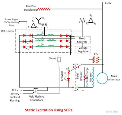
2) Static Excitation
- Supply is taken from alternator output to 3 phase star-delta connected to step down transformer.
- The primary of transformer is connected to alternator bus.
- The secondary of transformer supplies to rectifier, feed power to grid control circuit and other electrical equipment.
- Electric bank use for start up and being isolated after alternator output voltage and speed at rated as the static excitation use output from alternator.
- The CT and PT is fed to regulator to control thyristor bridge rectifier.
- Slip ring and Brushes is use to supply field current to rotor.
Alternator with Brushless Excitation System
AC Excitation with rotating rectifier(Brushless)
- Pilot Exciter Field, AC Exciter armature , rectifier diode, main alternator field rotates
- DC current feed directly from rotating rectifier to main rotor. This eliminates the use of slip ring and brushes.
- Pilot Exciter energize the field of AC Exciter, then the voltage regulator control AC Exciter field.
 |
| Brushless with PMG (Permanent Magnet Generator) |
 |
| Comparison DC, static and brushless exciter |
Typical Type of Brush & Brushless Motor
Brush Motor (Slip Ring Motor)
Have External Resistance Circuit for speed control.
Rotor Resistance Starter system can be available
High starting current.
for High starting torque.
also call as Phase wound motor.
Slot of rotor paralleled.
High cooper loss, (is winding loss, product of heat from electrical equipment).
Low power factor.
Brushless Motor (Squirrel Cage Motor)
No External Resistance Circuit as the bar of motor permanently slot & shorted at the end of the ring.
Rotor resistance Starter system unavailable.
Low starting current.
for Low starting torque equipment.
also call as cage motor.
Construction of Rotor is skewed, gives smooth torque curve, reduce humming noise and magnetic lock, increase resistance as the rotor length increase.
Low copper loss.
High power factor.
4) Synchronous & Asynchronous/ Induction Motor
Both are for AC motor only :
Synchronous/difference AC MOTOR/Induction or Asynchronous
Synchronous
- Rotor speed = rotating magnetic field(RMF)
- Stator supply with AC generates RMF
- Rotor can have DC external supply from slip ring or permanent magnet for it's own magnetic
- Rotor are designed to have equal or integral pole with stator.
- Thus the rotor & stator speed lock at same.
- Due to inertia Damper winding provided to overcome starting torque. It's act as induction motor during starting.
- Non self start; need mechanism either separately excited(DC source supply to rotor) or non excited(magnetize by rotational magnetic field from stator).
- Speed depend on frequency and number of poles, by VFD(variable frequency device) the speed can adjusted.
Induction or Asynchronous
- Rotor speed lesser than RMF speed, due to slip
- It's either squirrel cage or wound type rotor
- The stator RMF creates induce current into rotor. This cause rotor to have it's magnetic field.
- By Lenz law rotor magnetic field opposed the cause of it, (stator field)
- It can't run in synchronous speed as it need to slip by rotor try to catch up RMF from stator.
- It's depend on slip as the current induce in rotor is caused by change of magnetic field between rotor & stator.
- If it runs in synchronous the magnetic lock will occurs, no magnetic flux to induce current in rotor due to rotor & stator field not differ relatively.
- Induction motor can be single phase(not self start as it can't generates RMF as winding carry same current at various time, require extra mechanism) or three phase(self start as RMF creates by 3 different phase current frequency by 120 degrees difference)
5) Cylindrical & Salient Poles Rotor
Cylindrical Rotor
- Cylindrical or Drum rotor for high speed (1500-3000rpm).
- Smaller diameter, longer axial length, more robust.
- Less winding loss & noise.
- As speed is higher, number of poles range 2 to 4.
- Flux distribution is sinusoidal, gives better EMF waveform.
VS Salient Pole
- Salient pole for slow speed (100-1500rpm).
- Projected pole (made of laminated steel).
- Large diameter, short axial length.
- As speed is lower, more poles are require to achieve certain frequency.
f ; frequency of source(motor), frequency produce(alternator)
P ; number of poles
N ; Synchronous speed
- Need winding damper to prevent rotor oscillation.


Comments
Post a Comment